
Thanks to a couple of commenters, Stan and Johan, I can now add a little background information and a written reference to my record for this joint. The overwhelming evidence is that this joint has been historically employed primarily in applied moldings. Think paneled library, coffered ceilings and window mullions. A written reference to this joint can be found in “Woodwork Joints: How they are Set Out, How Made and Where Used. by William Fairham” on page 22, figures 49 and 50. Now that I have somewhat nailed down the historic use for this joint, let me address my earlier statement of strength.
In my first post on this joint I made a statement as to the strength of this joint. However, I failed to do so with any comparative or qualitative information. I have a tendency to be myopic in my woodworking. Focusing only on my unique applications and I apologize if my original statement caused confusion. I typically use stock that is 36mm(~1-1/2″) square in section. Mostly due to my attempt to use 2x construction lumber for my projects when possible. So my statement of strength is based upon this point of view. Therefore, when executed in 36mm(~1-1/2″) square stock, the thinnest section of material will still be a full 18mm(~3/4″) thick. Plenty of structural strength for most furniture applications. To further clarify, this joint is not stronger than other available options. So why bother? The joint does offer a couple of advantages.
The first advantage is the ability to have an overhang section, much like the top and bottom rails of my HB Tansus. This joint will allow the addition of mid-rails that mimic that look. The second advantage is the ability to chamfer the long edges before assembly.
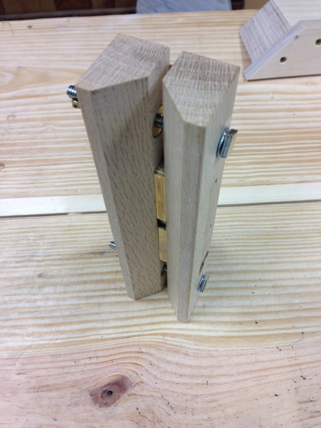
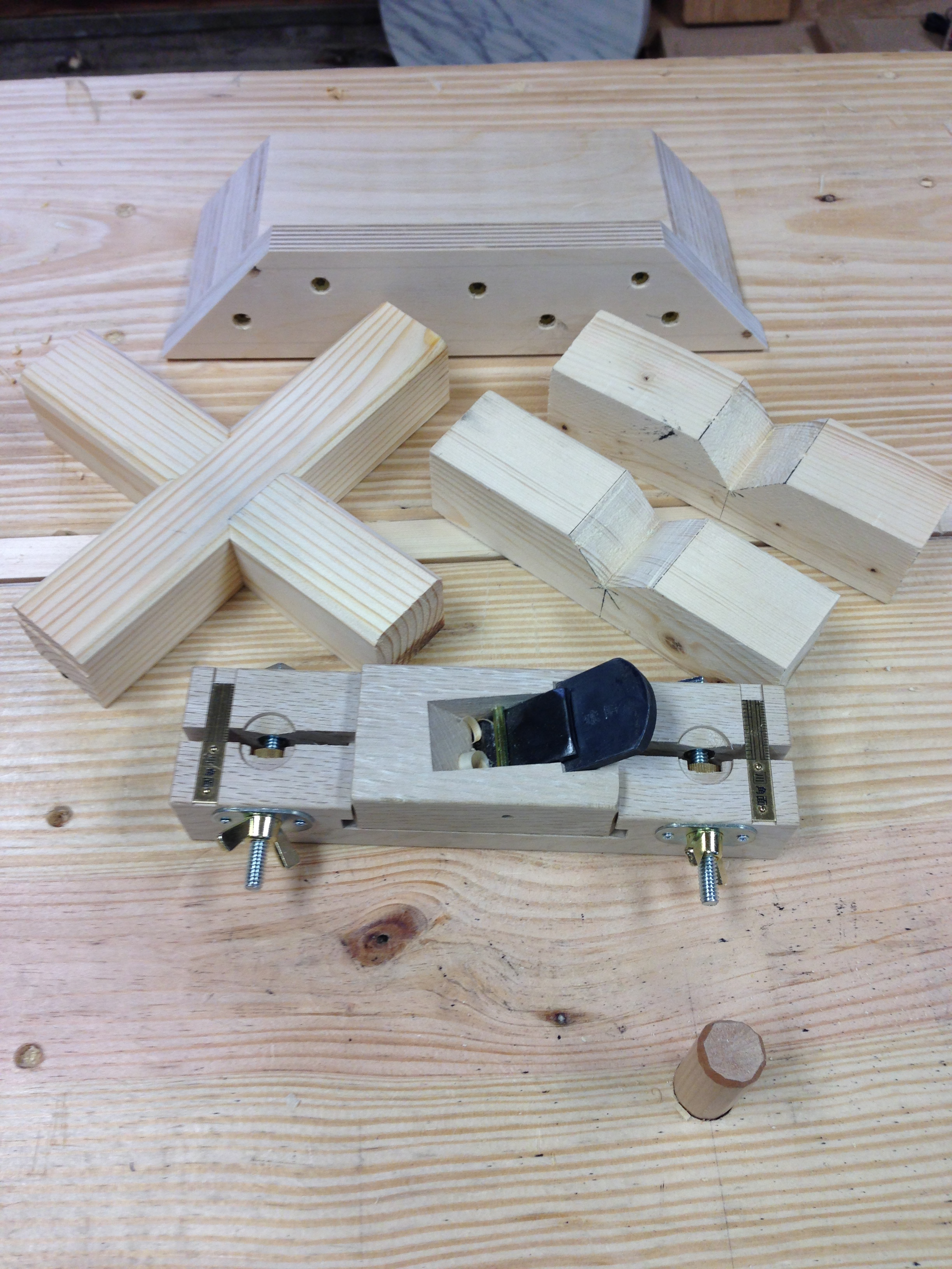
To make this joint easier to execute with consistent results there are few items that can be employed. To consistently pare the miters a jig can prove indispensable. The jig can be made from just about any piece of scrap. I plan to keep this jig for a while so my wood of choice needed to be stable and I chose to use birch plywood (see Stan’s warning in the comments below about using plywood for this). I glued two 3/4″ pieces face to face to yield a 1-1/2″ thick section and screwed an additional piece of ply to the edge of this to create a fence. Note that the fence extends above and below. This will allow me to use the jig on miters that slope away or slope under. Depending on need. Then I cut a 45° angle on both ends. By making the jig double-ended, I can pare miters in either direction while referenced from the same face of a workpiece. I used a power miter saw to cut the 45° angles and it felt a little like cheating, but it’s very accurate. Just to be sure though, I checked the angle on each end and also verified that the ends were square to the fence. The last thing that you want is a jig that is inaccurate.
For chamfering the long edges a cradle or multiple cradles can make the task much easier. The cradle is just a simple “V” block. A single long cradle can be made to match your workpiece or you can create several smaller blocks that can be spread along workpieces of varying lengths. You can use your bench stop to work against or you can build in a stop into the single cradle or into one of the multiple cradles. The “V” cut should form a 90° angle. In use, the cradle simply holds the workpiece so that the edge being chamfered is presented uppermost. Don’t underestimate the utility of this simple work holding aid.
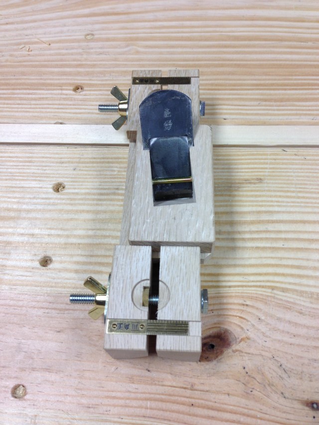
To further add accuracy and consistency a chamfering guide can be employed or you can utilize a specialty plane. I have a Japanese chamfering plane (mentori wanna) that I purchased almost a year ago but have never used before. It can be adjusted for width, the blade is skewed and the blade carrier can be moved side to side so that you can utilize the full width of the blade. This plane only does one thing, but it does it exceedingly well.

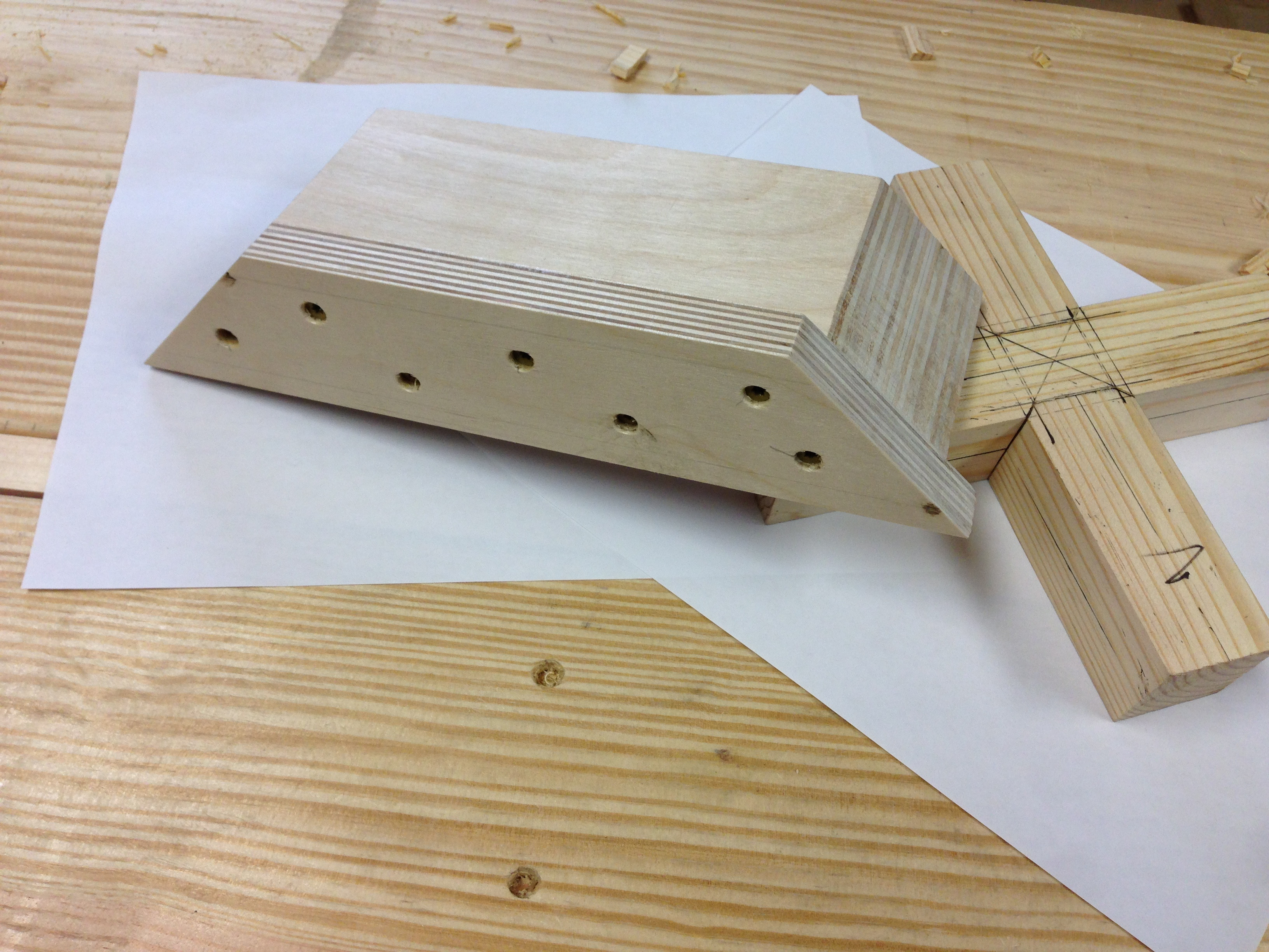
With all of the above in hand I had another go at this joint. I completed the layout and sawing just as I described in my first post. I want to emphasize the importance of making all of saw cuts to depth before removing any material. Once you start removing material, you start loosing layout lines. Leave the miters alone at this point though. With the saw cuts made, I removed the center section. Then I removed the waste from the sides. I was careful to leave my layout lines, save one. The depth of the lap I pared until I all but removed the layout line. Leaving just the faintest trace of the original line. In theory the two halves of the joint should meet at the middle of the depth line. By removing the bulk of the line, the joint should come together without bottoming out too early. Next I began work on the miters.
These are small miters. In a larger joint some of the miter waste could be removed with a saw. For my smaller work it was much easier to roughly pare away the bulk of the waste with a chisel. I then put my newly minted jig work. Working systematically, paring each miter. Checking for fit after each round. It took four rounds of paring before I achieved a fit that would allow the joint to be knocked together with a mallet. I have to say that the paring jig makes this joint much easier to execute accurately and resulted in a well fitted joint, IMHO.
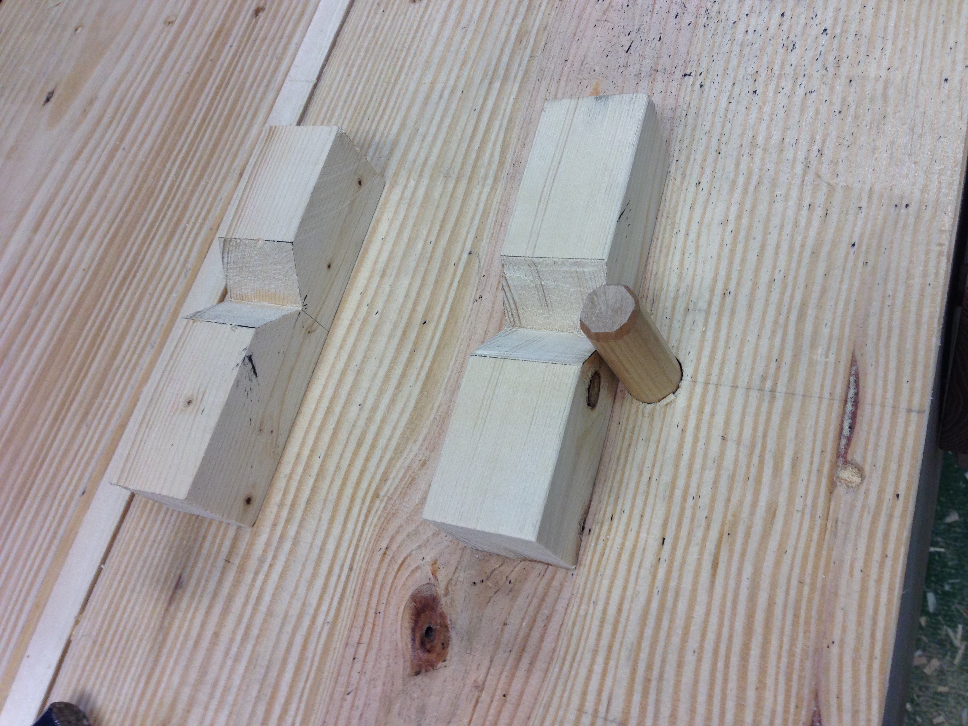
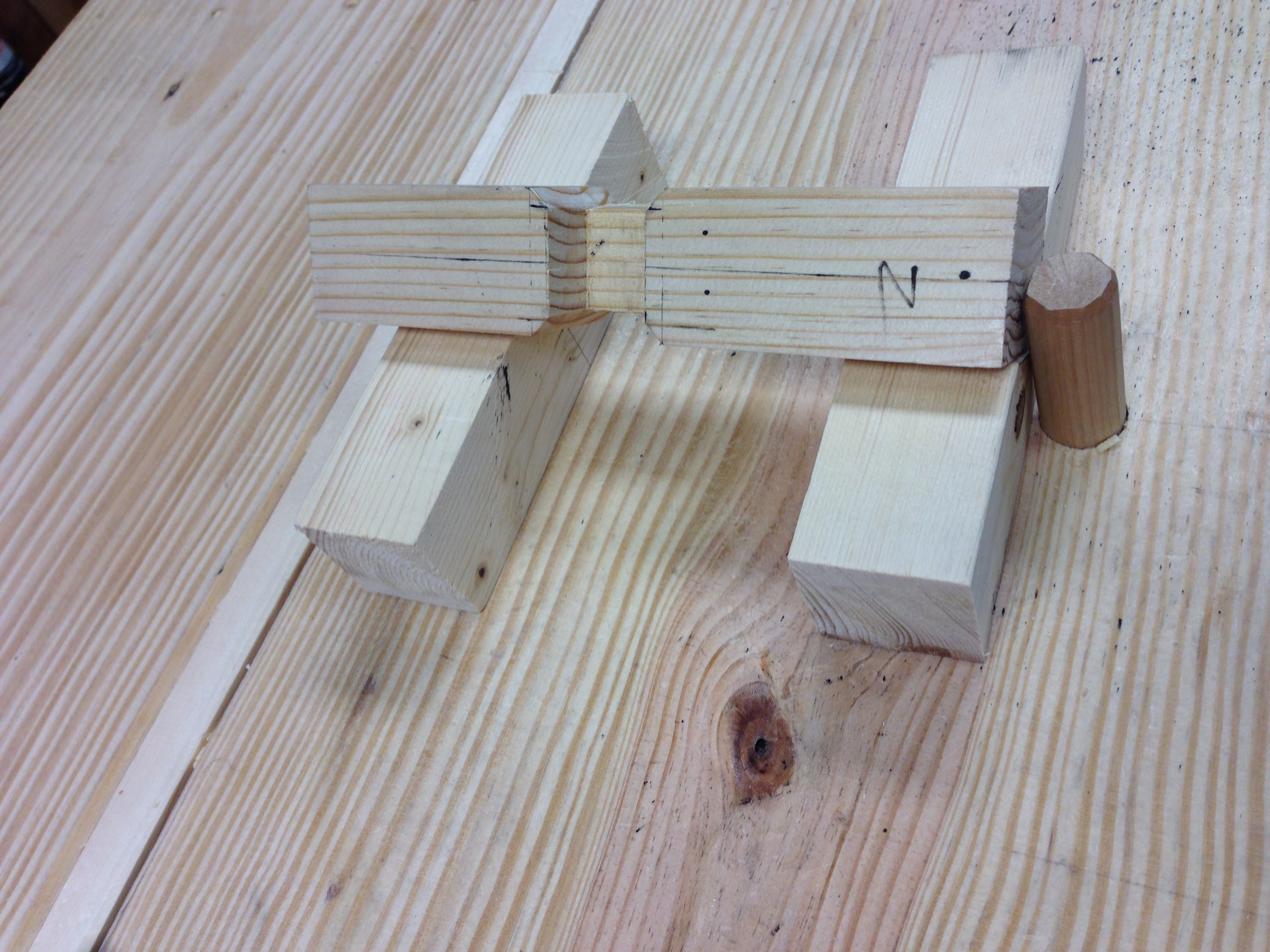
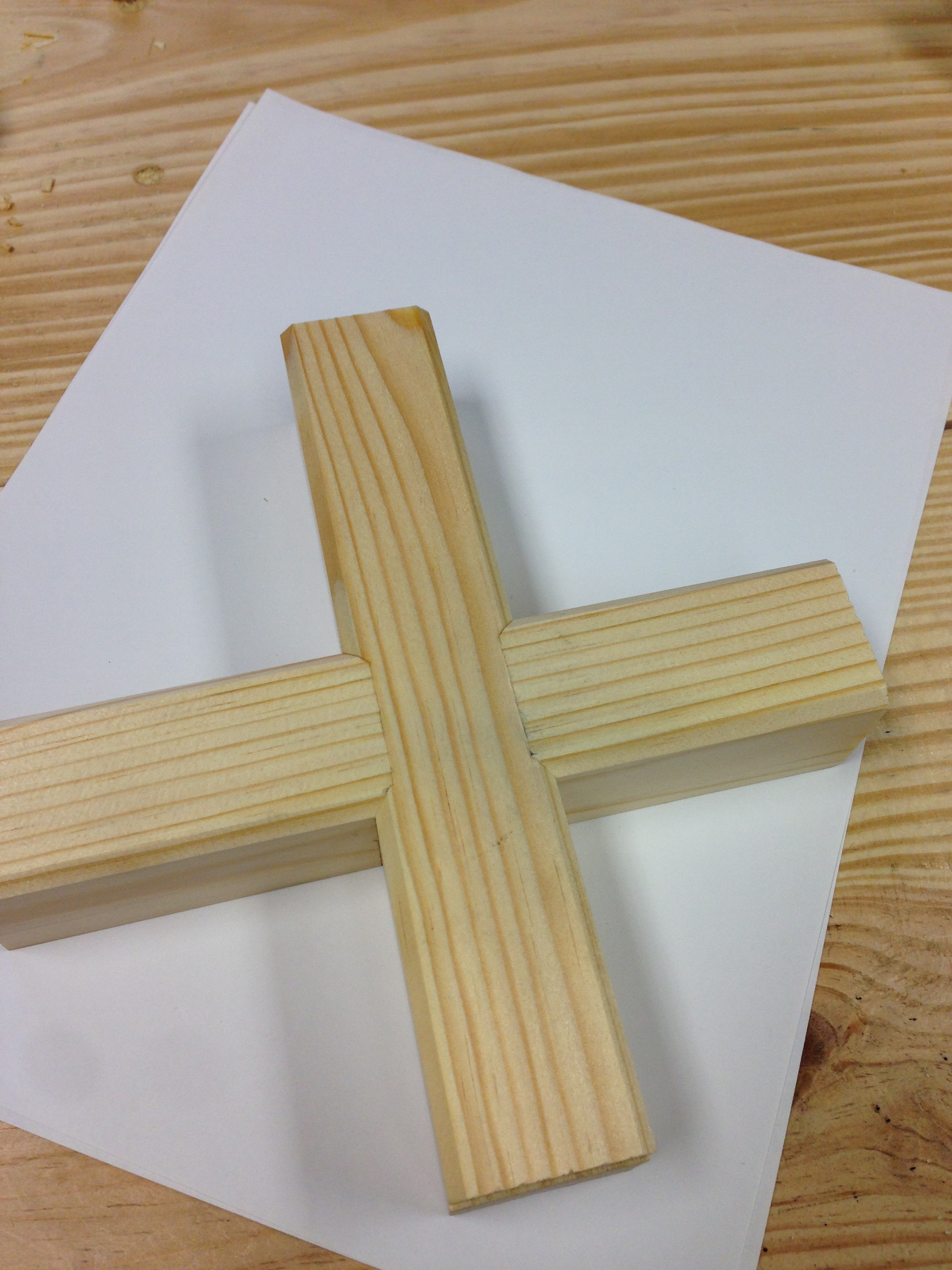
-
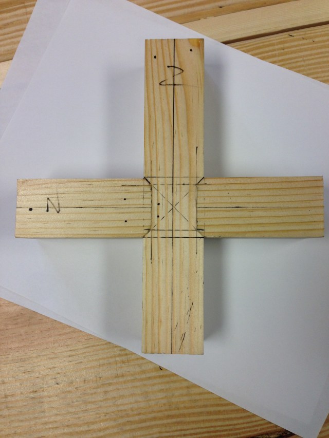
- Top of joint.
-
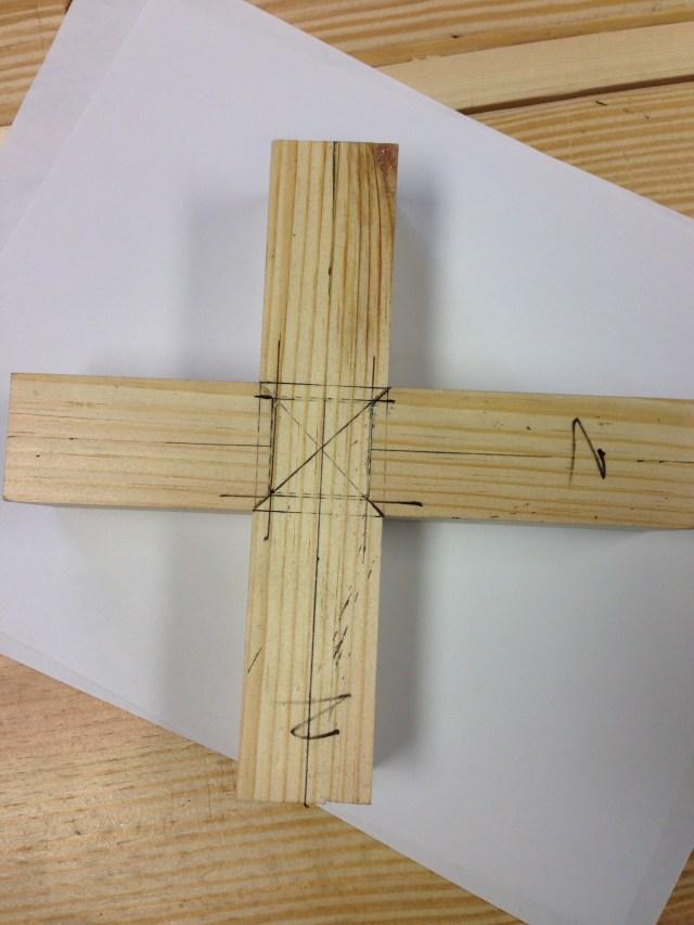
- Bottom of joint.
I then knocked the joint apart and set my chamfer plane to the desired width. The workpiece was then mounted in the “V” blocks and a chamfer was planed on all of the long corners. The chamfer plane is a fun tool to use and is very accurate, but you can get by with just about any plane as long as your careful.
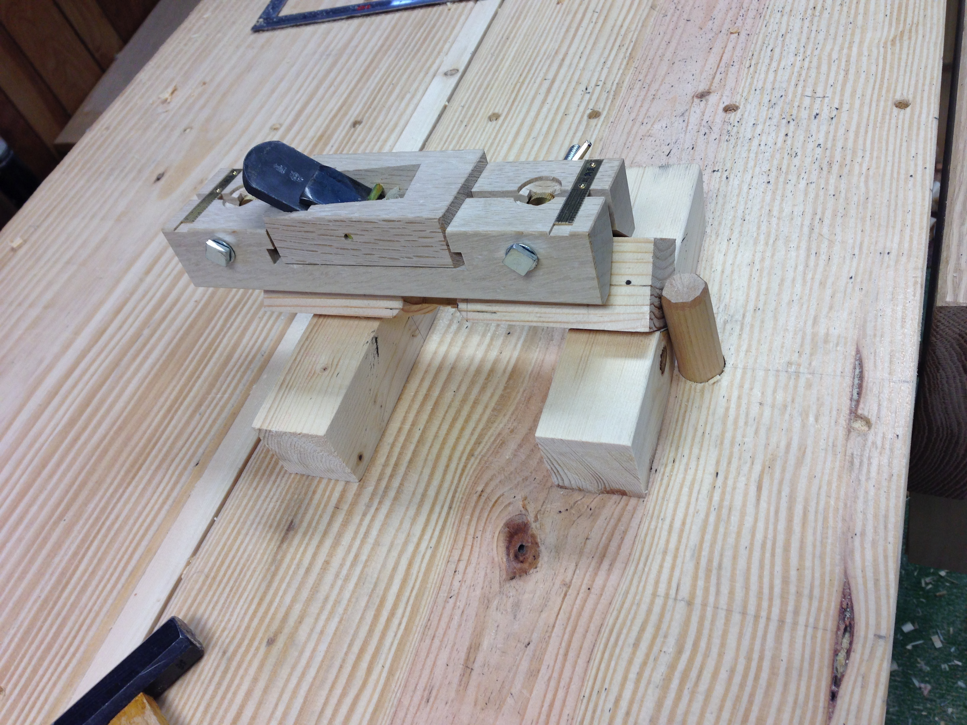
With the chamfers in place, I reassembled the joint. Not too shabby for try #6, if I do say so myself.
I hope that the above information adds a little clarity to the history and execution of this joint. I also hope that, like myself, you give some thought to using this joint in unconventional applications. At the very least, I hope that you make a few examples just for the fun of it.
Part 1 Greg Merritt

Pingback: Cross Lap with Mitered Corners-Part 1 | GREG MERRITT – BY MY OWN HANDS
Two points you might find worthwhile. First, as I noted in my earlier post, this joint is standard in Japanese timber frame construction, and one Japanese Daiku involved in such work must learn. The most common location is where the top plates, or beams, supported by columns intersect and cross at a structure’s corners. The reasons for using this joint at this location despite the loss in strength and additional work is worth investigating.
Second, just an observation on your jig. Excellent design. Plywood, while stable, is not the best choice because plywood is manufactured using large sanding machines, and ALWAYS has large amounts of hard grit embedded in the wood fibers. This grit will scratch precious chisels, making them difficult to maintain at peak sharpness.
Sorry Stan, I missed the connection to timber framing with your reference to “wooden religious structures”. I’m most interested in learning more and I would be greatful if you could point me towards any reference that you may be aware of. So far I have come up empty. I must be looking in the wrong places.
I hadn’t considered that plywood would have embeded grit. I guess I’ll need to consider making a new jig. At least it is a fairly simple operation. Thanks for the warning.
One last thing…please don’t take offense at the name of my website. It is intended as a play on words. Hilllbilly (unsofisicated, poorly educated) + daiku (loosely translated as carpenter).
No offense taken. I think I caught the play on words.
The links below show some examples of this joint used in movable “Yatai” or “Mikoshi” carried during religious festivals. There are better examples in books, but they are hard to post online. http://yamamotokenchiku8101.hamazo.tv/d2011-08-22.html
Another application is fancy ceilings. The following link show how to do an oriage koshitenjou without using the mitre. http://blog.livedoor.jp/hamanaka_syouten/archives/29973564.html This can be done with a shaper or router, but is cheating in the eyes of those that know about such things.
The following link shows how to do it right. http://kino-ie.net/interview_212.html
Here is a link to some pics by a joinery company (doors and windows) that fabricates simpler, but still elegant, IMO, ceiling latticework (koshitenjou). http://www.gouten.jp/main/サル棒面格天セット価格表/
Another page: http://www.ohkatsu.co.jp/02.htm
A truly excellent and useful joint.
Stan
Thank you!….wow!
Attempt #6 looks really, really good to my eye. It is amazing what a little practice will do. Thanks for posting pics of your first attempts.
Thanks Brian. I feel that it is important to show the process, warts and all. I think it helps cut down some of the frustration for others who may try the joint. It is rare that our first attempts at anything turn out “perfectly”.
I still have a ways to go before I reach a comfort level with this joint though.
I might never use this type of joint, but I have to heap praise on your tooling efforts (even if the did use plywood). Impressive! Hey, we all know a guy who does these sorts of things in stainless (and aluminum) and sells them for thousands. Just sayin….
LOL…just a chunk of wood with a miter cut on both ends.
It is not a joint that I’ll use often, but it will come in handy when I need it.
You almost lose me here….
How can you…???
This quest is about wooden joints and you used screws on your jig… what a shame! lol
You should put an super “extra fancy extraordinary awesome Supercalifragilisticexpialidocious” joint on that jig”
Get back to the shop and do it again to save the honor of this blog.
Rosa is near me laughing, hope this make you smile!
Great work!
Have a great day!
😉 🙂 …I’ll try to do better next….I promise.
grow up it’s ok to evolve from time to time like everything does
I believe this joint is stronger than a plain cross lapped joint. The increased surface area at the contact point spreads the fiber compression over a larger area (pulling two legs together – torsional). Granted I don’t believe I have seen any cross lap joints bear load in this axis.
I believe that the mitered corners do add a bitt of strength over the plain cross lap version. The increase is probably negligible for furniture scale work though.