
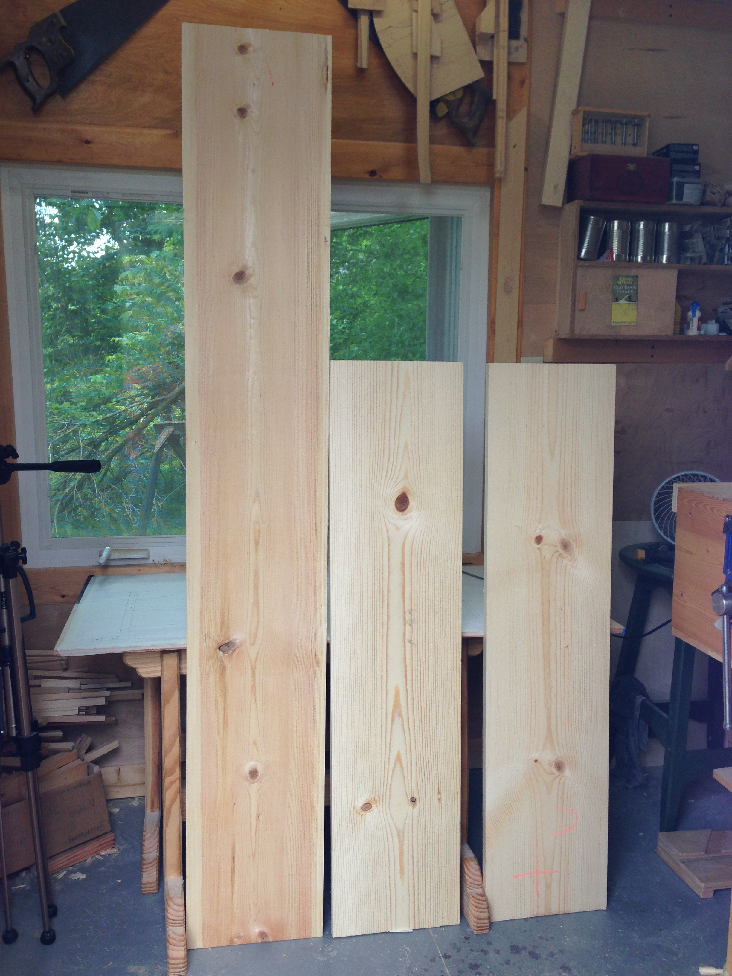
 A trip to the Home Depot resulted in a decent haul. After rooting thru the stacks of #2 mystery pine, I managed to pull out one 1x12x6′ and two 1x12x4′ boards that should yield all of the timber needed for this project. I’m not overly picky when going thru the stacks. It’s #2 grade after all. I typically reject any boards with knots on their edges. Any with loose knots and any that show signs of a twist. I learned that lesson long ago with this marginal lumber. No matter what I did to remove twist from a board, it kept coming back. Not good and not worth the hassle. Anyway, here is what a drug home.
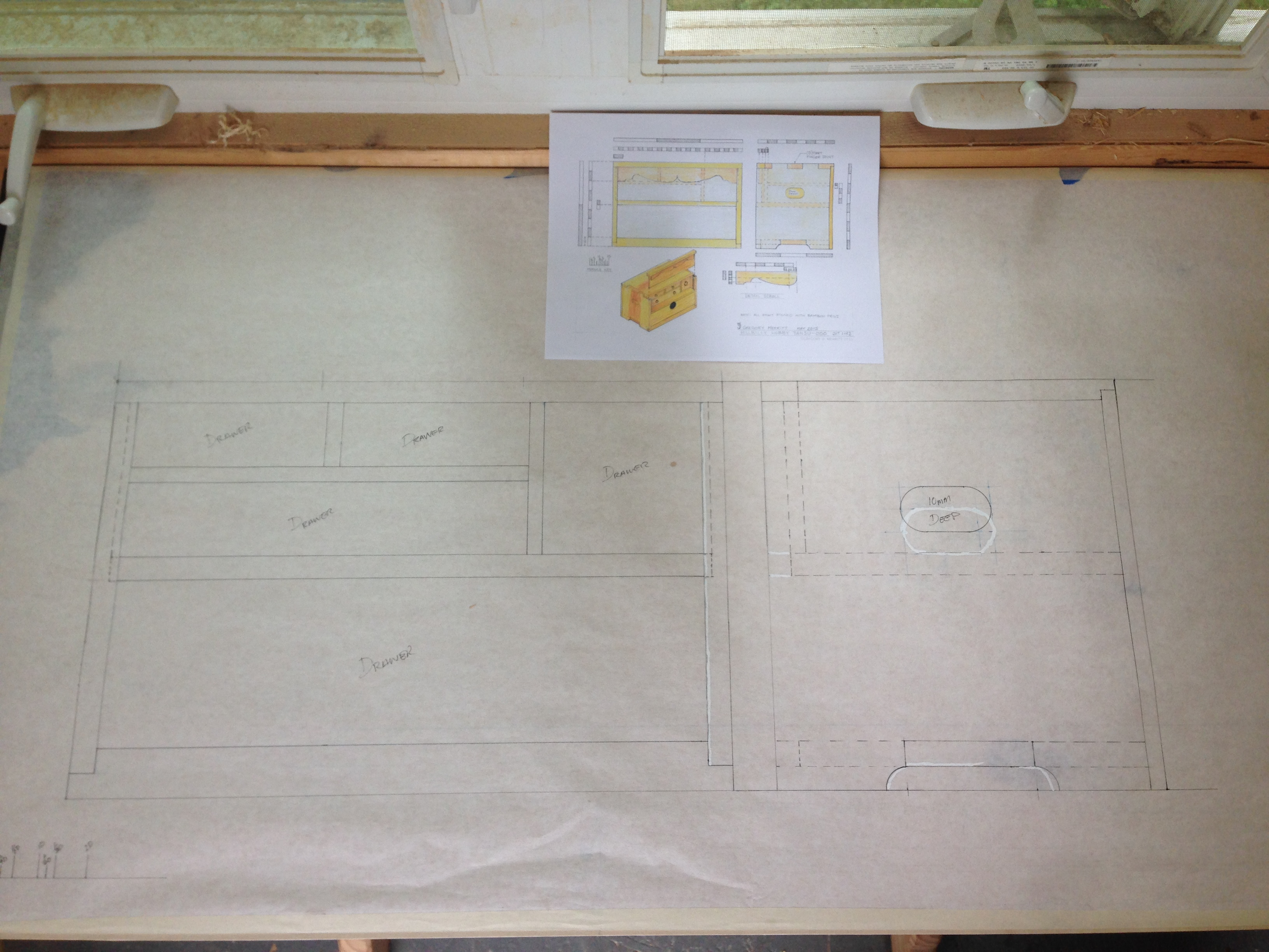
The first order of business this morning was to convert my proportional drawing into a working full-size shop drawing. I’ve talked about this before, but it’s worth repeating. I design with proportions to make scaling a project much easier. For example. Let’s say I want one of these boxes to be a specific height. I’ll simply plug in that height and use the dividers to break that distance down to find all of the other distances. So, suppose the required height is 15-3/4″. The design drawing shows that the proportional height of the box is 9D (modules). Therefore, 15.75/9=1-3/4″. Then I would create a module key based on 1-3/4″ and then simply step of all the other distances.
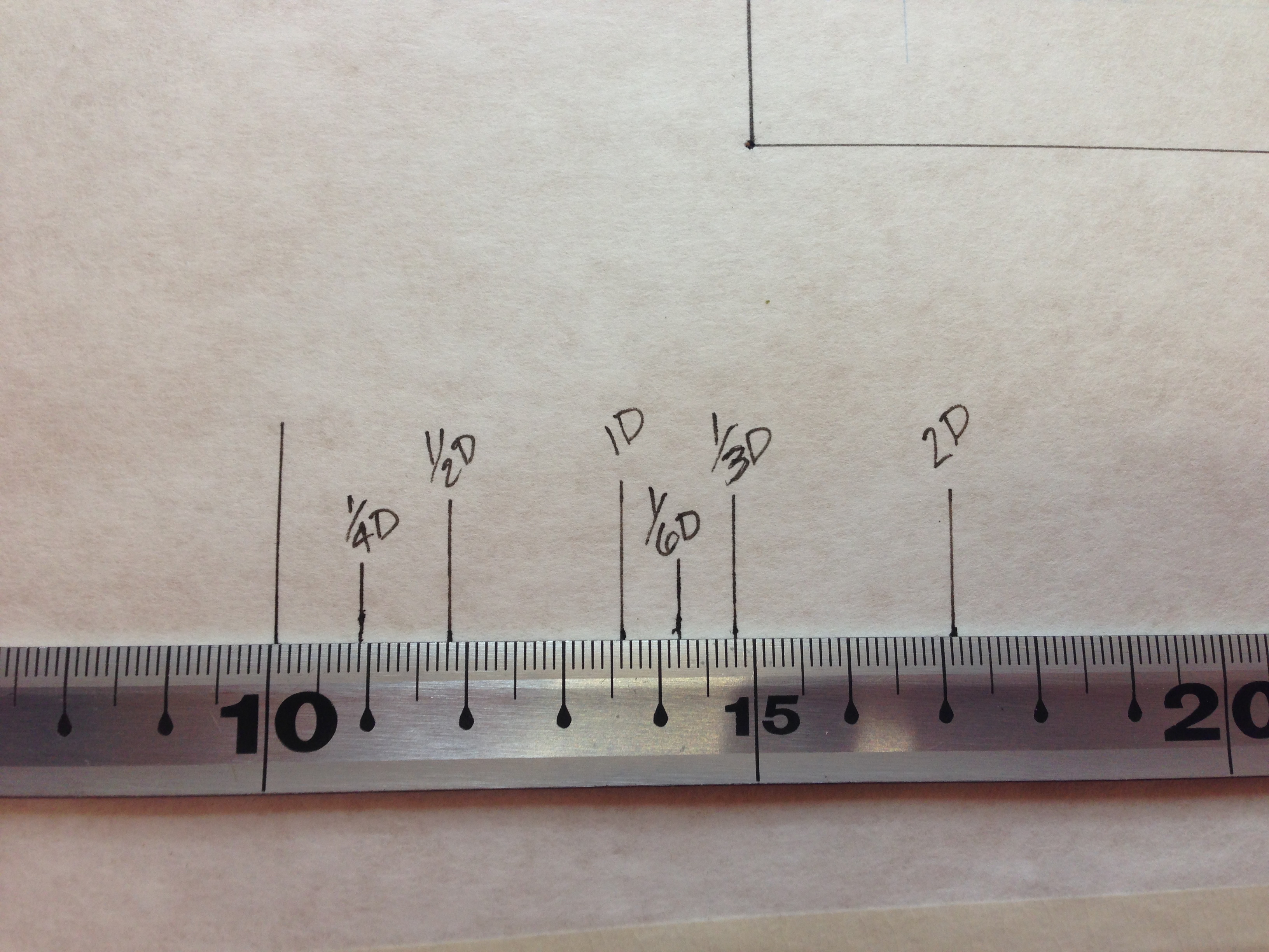
For this project I’m using my usual 36mm for the module. To start the full-size drawing I first created a module key based on 36mm.
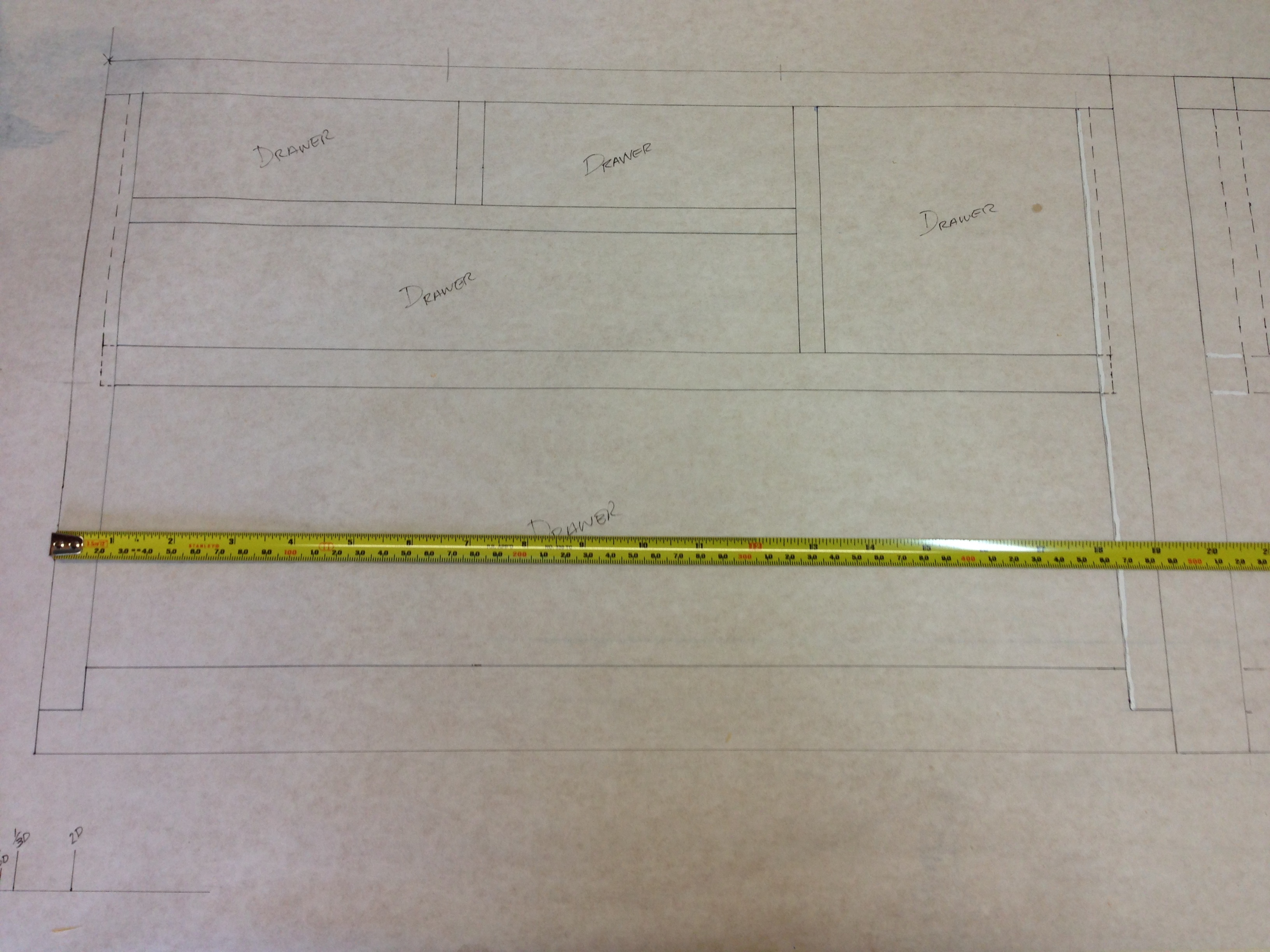
Once the module key was established it was quick and easy to step off all of the required distances. Well…mostly. I had a couple of missteps as evidenced by the presence of correction fluid on my drawing.
So you can have an idea of scale.


So why do I design around 36mm? Simply because it breaks down into the standard thickness of timber as well as the widths of chisels that I own. i.e. 6mm, 9mm, 12mm, and 18mm. No magic involved just practicality. I also find that any scaling of a project rarely changes the material thickness enough to warrant matching the resultant scaled thicknesses. That’s probably clear as mud. It’s far easier to do than to explain. Just shoot me questions if you want to know more or need clarity.
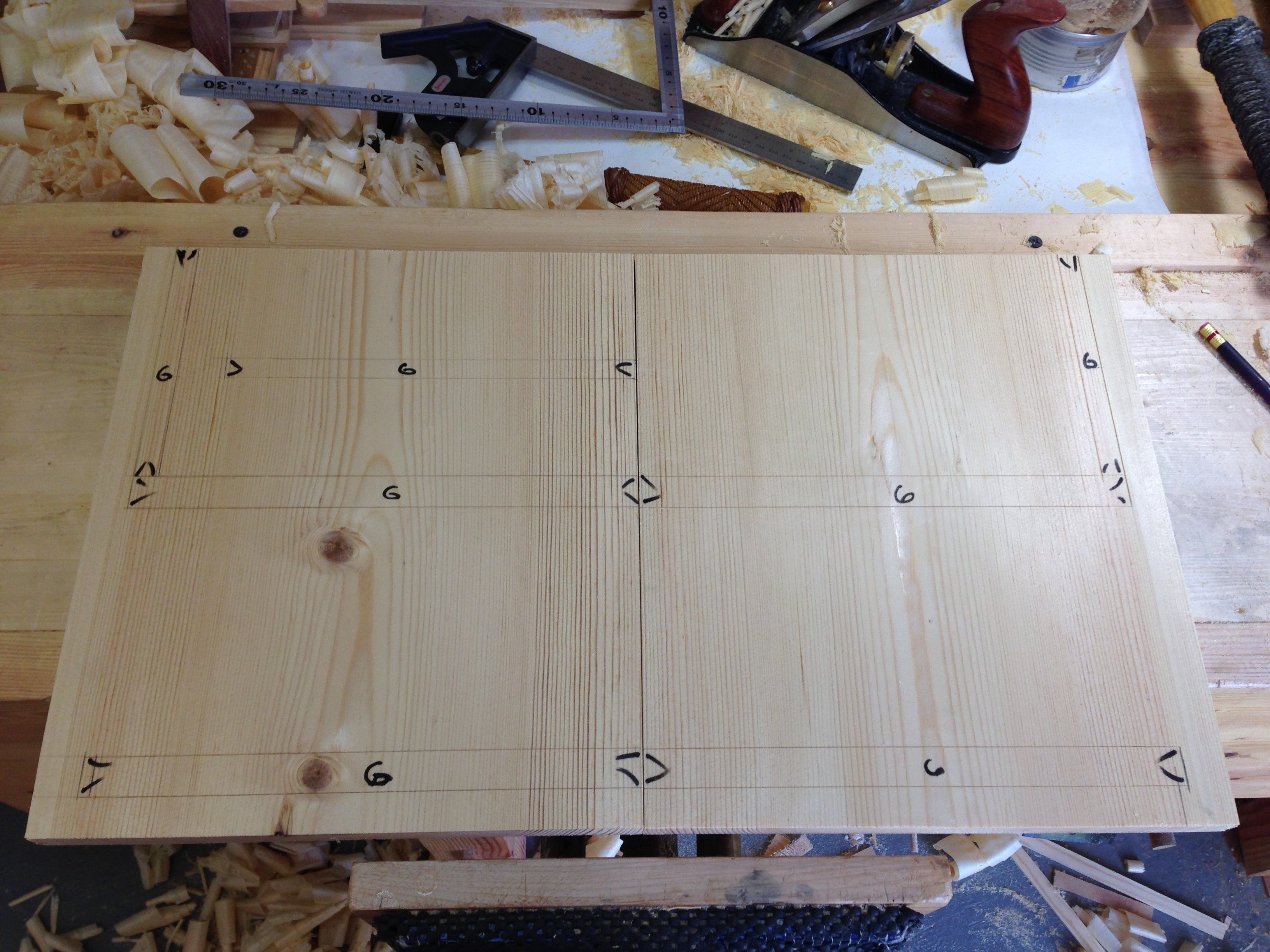
I purchased the 6′ board so that I could fabricate the entire outer case with the grain running continuously around the box. Starting at one end of the board I laid out the end, then the top, then the other end and finally the bottom. I paid particular attention to the knots. The last this you want is to try to cut joinery thru a knot. I was able to avoid almost all of them. The only knot that landed on a joint fell in the waste portion of a finger joint on one of the end panels. Sometimes I get lucky.
I apologize for the lack of progress photos. Since this is a new design I was concentrating on not screwing it up.
The next step was to surface plane and then square the ends of all the pieces on the shooting board. The ends were made to be the exact same height and width. The bottom and top received the same treatment.
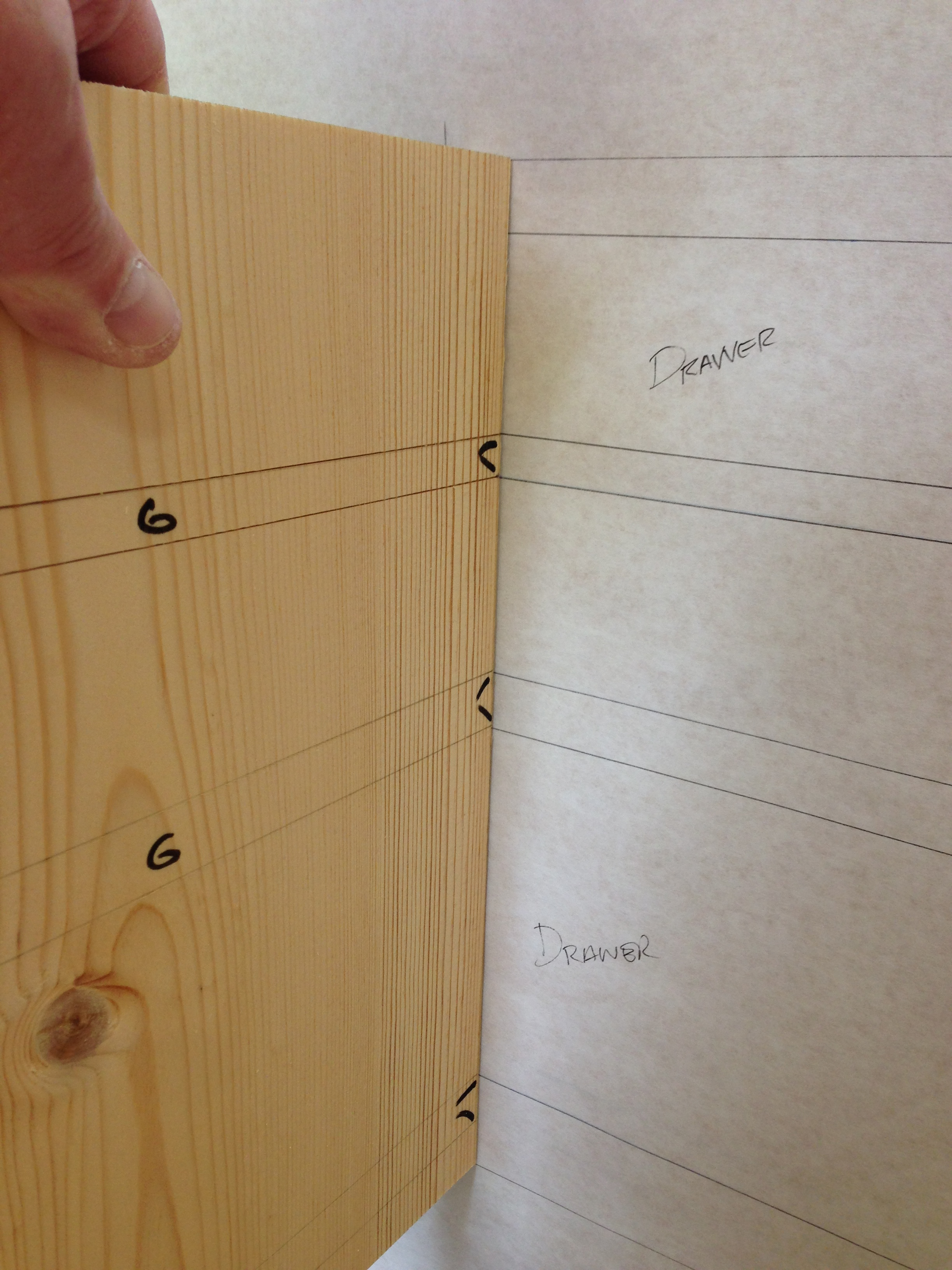
I began the joinery with the dados in the end pieces. Marking one end panel directly from the full-size drawing and then ganging it with the opposite end panel to transfer the marks.
Dados marked and ready to be cut.
Never hurts to double-check against the drawing.
There are multiple ways to cut a dado joint. The end result is all that matters not how you got there. For the record, I knifed, then chopped, then pared and finally leveled the bottoms with a router plane.
The top is joined to the sides with a 5-part finger joint. For this I simply used a pair of dividers and trial and error until I had them set to exactly 1/5 the depth of the box. The bottom is joined to the sides with a 3-part finger joint. The front and rear portion of which are housed in the dados.
Cutting finger joints is no different than thru dovetails. Less the angles of course. Mark, saw and chop the portions on one piece and transfer to the mating piece and repeat. I’m working in pine and wood compression is my friend. The housed portion of the bottom added a little extra chance of screwing it up but not too much.

Up to this point I left all of the pieces the exact same width. I think this made it much easier to keeping the joinery layout correct. The top still needs the front trimmed back to make way for the lift out front panel and it needs a rebate at the rear to house the back panels. The end panels need their width reduced at the rear to make way for the back panels as well. I already trimmed the front edge of the bottom panel to make way for the skirt. If I had made all the pieces their finished width from the start, I guarantee that I would have made a mess of the joinery.

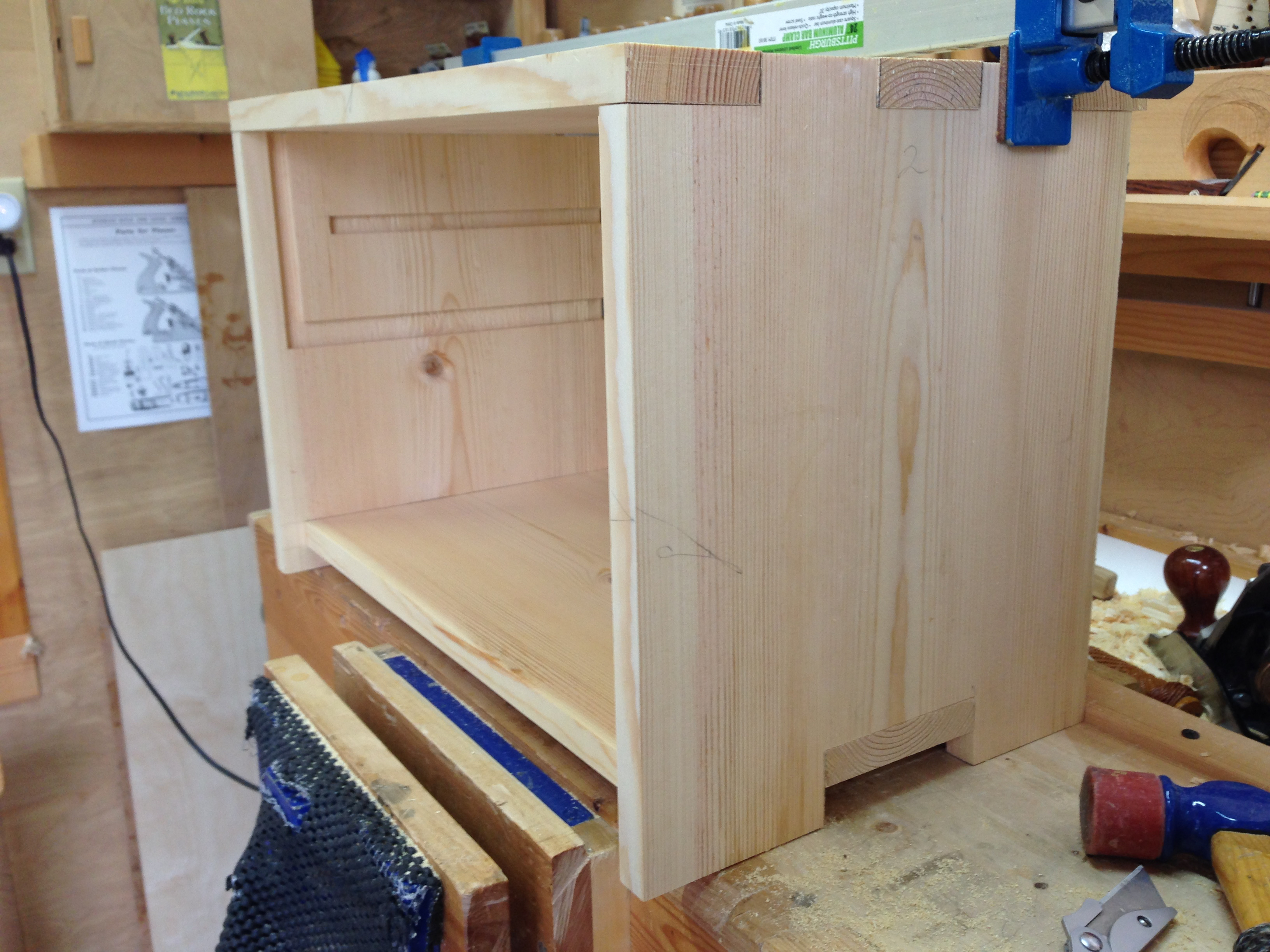
Not a bad start if I do say so myself. I’ll piece at it this week after work as time permits and go at it hard again next weekend.

Pingback: HB Hobby Tansu #1-Part 2 | GREG MERRITT – BY MY OWN HANDS
Nice to see second grade lumber used for such concise, sensitive work. As The Schwarz once said, “it’s amazing what you can do with humble materials and tools.”
One of my goals here is to show others that they can build decent furniture with commonly available materials. Walnut, mahogany, cherry and the like are great, but not everyone has access nor can afford those species. Hopefully what I’m doing will show others that they can build projects with what they have access to and can afford.
I really like the proportional design concept. Will it scale to a rational system like feet and inches?
Inches, millimeters, furlongs, cubits, the distance cares not what you label it. I use a numeric value to more easily convey the idea here on the blog, but could just as easily have used the length of my thumb. The design itself is based upon whole number ratios. For this project the front elevation is 2:3. Two units high by three units long. The end view is 1:1. Although I cheated it a little to make use of a nominal 1×12. With a pair of dividers and a sheet of paper, I can play with designs until I like the look. Then start breaking them down to find the module(D). Practically any distance can be used for (D). The end product will vary in physical size, but all iterations will look identical. Hence the scalability. If I lay out the project full-scale and find it too large or small, I only need to adjust (D) accordingly and lay out a new full-scale drawing. It’s rare that I every use an actual numeric distance when I’m actually building a project. Everything is either taken directly from the drawing, stepped off with dividers or taken directly from the project (i.e. drawer fronts).
Have you read “By Hand and Eye“? If not I highly recommend it. It completely changed the way I work.
I have played around with proportional systems for a long time, fascinating stuff. Haven’t read that particular book, but will check it out if it comes along. I was really taken with “The Old Way of Seeing” until the chapter on modernism…What I really want to do is make a tracing floor like the medieval architects had, and work out some drawings at that scale.
For most of my adult life I have been convinced that we, as a civilization, have lost some bit of information that allowed our predecessors to design and build with both beauty and precision. Physically manipulating distances with dividers or knotted ropes is a part of it, IMHO. Lofting floors in boatbuilding is a remnant I think. I believe there is something similar in timber framing. Not sure what its called.
How was trigonometry developed before the introduction of Arabic (Indian) numerals?
Develop a quadrant of a unit circle, and impose all the basic proportional triangles, Fibonacci’s numbers tend toward 32º. Could 32º be a cipher for understanding all that, as a pentagram implies understanding how to derive golden mean from a square?
http://michaellangford.org/2013/08/05/rhenish-helm/ I didn’t include the drawings with this (pencil lines are hard to photo) but the design is basically an equilateral triangle superimposed on another equilateral on a square plan. Origins are (so far as I know, Saxon/Baltic/Germanic) from the early Romanesque. I believe the dramatic change occurred with Templars, bringing back advanced mathematics, coffee, sugar, and hashish. Freemasonry now is just a confusing and diluted ritual, the important stuff obscured and forgotten.
Exactly! Numbers are great for theoretical, but seem to fall short in practice. Very high levels of mathematics can be accomplished with geometry with little need for understanding the “theory” of why it works. We used to focus on the result, the real world application. Now theory is the focus with almost no regard for application.
The timber framing in your linked post is fantastic. Simple shapes manipulated for strength, beauty and function. I’m fascinated by timber framing. High level geometry executed in wood on a large scale. What’s not to like?
You’ll have to help me with the correlation of 32º and Fibonacci. Admittedly, the first thing that came to mind was 32deg Freemason.
Operative masons were entered apprentice, fellow craft, master mason. Higher degrees were all honorary, based on memorizing esoterica. Cryptic cognates…mnemonics.
On a ++ trig quadrant, if you construct angles represented by the few triangles that can be solved by integers and the square roots of counting numbers, 1:1, 1:2, 1:2 (half an equilateral) 2:3, 3:4:5…1:1.618 falls almost exactly in the middle of that spread at 31.72º (hence 32nd degree). The arcs on either side of that line are thus 2º, 3º, 5º, 8º, 13º (by addition). 5:12:13 (part of an octagon) is 22.5º. By graphing sine and cosine, a number line develops…
Timber framing: until early 19th c. Americans developed square rule (and ship’s lines) with Cartesian principles, all framing was laid out on a ground plan and lofted with a plumb line. European builders would still have been using models and scaling measurements with dividers.
Now I see. I’m going to half to play with that a little and see if anything jumps out at me. Thanks.
Still have not ventured into the full scale drawings, been on a bit of a hiatus with wood things lately….by the by…. Some guy named paul sellers also thinks cherry is nice to work in according to todays post……
Who?…LOL…that guy just might make something of himself.
Pingback: HB Hobby Tansu #1-Part 4 | GREG MERRITT – BY MY OWN HANDS